The Total Quality System is based on three main pillars: Training, Communication and Participation. Training enables people to do their job, to make improvements, and to make decisions. Communication conveys the company’s objectives and policies, and makes people identify with it. Participation incorporates all the contributions by people in the company.
1. Overview of Optical Image Screening Machine
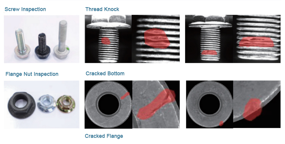
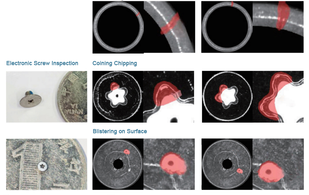
Optical image screening machine, namely machine vision inspection machine. Optical image screening machine is a new type of automatic screw and nut inspection and screening equipment. It is mainly used to replace manual size inspection, appearance inspection and defect inspection of various types of fasteners. It can automatically complete feeding, inspection, quality discrimination and screening. It greatly improves the detection accuracy and detection speed of the appearance and size of fasteners, and greatly reduces the cost of manual detection.
2. The working principle of optical image screening machine
The CCD image control system is used as the main control unit, using displacement and visual sensing technology, according to the screw and nut parameters, to automatically complete the feeding, detection, and discrimination, and finally automatically screen out the good and bad products.
With the development and upgrading of the domestic industry, all kinds of precision parts (such as automotive screws, electronic screws) need to be fully inspected for appearance and dimensional quality. Manual visual inspection for a long time makes the eyes easy to fatigue, resulting in low product inspection efficiency and low accuracy. Replacing artificial vision with machine vision can greatly improve production efficiency and inspection accuracy, reduce customer complaints, and reduce labor costs.
3. Technical characteristics of optical image screening machine
- Automatic CCD visual inspection to reduce the cost of manual inspection;
- High detection accuracy, the highest detection accuracy is ±0.005mm;
- There are many testing items and a wide testing range;
- Fast detection speed, the fastest detection speed is 1200 pieces/min;
4. Screenable objects of optical image screening machine
Screws, nuts, hardware accessories, mobile phone accessories, auto parts, small screws, precision screws, gaskets, special-shaped parts, stamping parts, injection parts, galvanized screws, precision hardware, etc. It can also be reasonably customized according to the shape and size of the object.
5. Testing items of screw optical image screening machine
Cracks, burrs, head text/shape, length, diameter, whether there is a cut tail, pinhole concentricity/roundness, whether the screw and nut have teeth, the inner and outer diameter of the screw, the pitch of the screw, the angle of the screw, and the poor grinding , bottom shape, tailing, bending, tail cutting groove, multi-section height/width/thickness, chamfer/angle, number of teeth, surface contamination, surface defect, imprint, surface defect, etc.


We know that our customers count on us to provide dock-to-dock reliability and superior C-part delivery for component needs. If we don’t make it easier for you, there’s no point in you partnering with us. We take this mandate very seriously and offer a variety of types of quality assurance.
Spectral Analysis

Product Description.
The culmination of the research and development and production experience of infrared microscopes has achieved unparalleled high stability and reliability with its high-quality design in optical components, mechanical processing and electronic circuits. The modular design can be carried out according to your needs. Customized to meet a variety of challenging R&D research jobs. Its application fields are very wide, covering materials science research, polymers, chemical products, forensic criminal investigation, art protection and life sciences. The microscope has various means of contrast illumination enhancement, various infrared lenses and chemical imaging functions, allowing users to easily and efficiently complete various high-sensitivity microscopic analyses..
Process.
1. Turn on the power of the spectrometer..
2. Turn on the computer power.
3. Press the UV WinLab icon with the mouse in the file manager, and the UV WinLab application window will appear. The instrument is ready, and an appropriate method can be used for analysis.
4. In the analysis, some necessary parameters must be set for the spectrophotometer. The combination of these parameters forms a "method", scanning, time driving, wavelength programming (WP), concentration (CONC)
5. After the scanning, time-driven, and wavelength programming method is selected, first put in the reference solution, press the AUTOZERO key, and then put in the sample after automatic zero calibration or background calibration, and press START, the spectrophotometer starts to run, and at the same time. A graph window appears on the screen, displaying the results
Salt Spray Test

Product Description.
The salt spray test standard is a clear and specific regulation for the salt spray test conditions, such as temperature, humidity, sodium chloride solution concentration and pH value, etc. In addition, it also puts forward technical requirements for the performance of the salt spray test chamber. The judgment methods of the salt spray test results include: rating judgment method, weighing judgment method, corrosive substance appearance judgment method, and corrosion data statistical analysis method. The products that need to be subjected to the salt spray test are mainly some metal products, and the corrosion resistance of the products is investigated by testing..
Process.
1: The specimen should be thoroughly cleaned before testing. The cleaning method used will depend on the nature of the material, its surface and contamination, but must not use any abrasives or solvents that could affect the surface of the specimen. Generally, ethanol can be used to clean, or magnesium oxide solution can be used.
2: Place the sample
3: Record the initial time of the test, and it is forbidden to open the lid or stop the salt spray test during the test.
4: Record the end time, and measure the collected liquid collection volume, pH, specific gravity and other information.
5: When the laboratory temperature has cooled to room temperature and is basically free of fog, take the product out of the test chamber, rinse the product surface with warm water not higher than 38 ℃ for 1 minute (clean), and then blow the product surface clean with an air gun. Place it at room temperature, wear clean cotton gloves, check the appearance of the sample to be tested under 1000LUX light, and conduct the salt spray test result identification
Coating Test
Product Description.
A mechanical property test to measure the surface hardness of solid materials. There are scratch method, press-in method and dynamic method. There are three types of indentation hardness tests commonly used in mechanical engineering: Brinell hardness, Rockwell hardness and Vickers hardness. The test can be carried out directly on the parts, and the traces left on the surface are small, and the parts will not be damaged. The method is simple, fast. It is widely used in the machinery industry to inspect the quality of raw materials and parts after heat treatment..
Process.
1: The object to be detected should be placed flat on the ground, and it must be perfectly stable, without any shaking, and the detected position should not be in a suspended state, and a support block should be added if necessary;.
2: Open the hardness tester→the material setting of the object→hardness value setting (HRC\HRB\HB)→hardness detection direction setting→start hardness detection.
3: Press the impact device against the surface to be tested and press it down, and then press the small cylinder protruding from the hardness tester after 1s, the hardness value will be automatically displayed, during this process, the operator must stabilize the impact device , the direction should also be vertical to the measured surface.
4: At least 3 points should be tested for each test part, and the distance between the two test points should be ≥3mm. After the test, the average value is taken as the hardness of the part, and recorded, and then the next part is tested.
5: The test results are compared with the requirements of the object, and if the requirements are met, they will be transferred to the next process; if they are not qualified, they will be transferred to the isolation area and the test results will be recorded.
Universal Tensile Test
Product Description.
Tensile testing refers to a test method for determining the properties of a material under an axial tensile load. Using the data obtained from the tensile test, the elastic limit, elongation, elastic modulus, proportional limit, area reduction, tensile strength, yield point, yield strength and other tensile properties of the material can be determined. Creep data can be obtained from tensile tests conducted at elevated temperatures. The procedure for tensile testing of metals can be found in the ASTM E-8 standard. Methods for tensile testing of plastics are described in ASTM D-638, D-2289 (high strain rate), and D-882 (sheet). ASTM D-2343 standard specifies the tensile test method applicable to glass fibers; ASTM D-897 standard specifies the tensile test method applicable to adhesives; ASTM D-412 standard specifies the tensile test for hard rubber method.
Process.
Product Description.
A mechanical property test to measure the surface hardness of solid materials. There are scratch method, press-in method and dynamic method. There are three types of indentation hardness tests commonly used in mechanical engineering: Brinell hardness, Rockwell hardness and Vickers hardness. The test can be carried out directly on the parts, and the traces left on the surface are small, and the parts will not be damaged. The method is simple, fast. It is widely used in the machinery industry to inspect the quality of raw materials and parts after heat treatment..
Process.
1: The object to be detected should be placed flat on the ground, and it must be perfectly stable, without any shaking, and the detected position should not be in a suspended state, and a support block should be added if necessary;.
2: Open the hardness tester→the material setting of the object→hardness value setting (HRC\HRB\HB)→hardness detection direction setting→start hardness detection.
3: Press the impact device against the surface to be tested and press it down, and then press the small cylinder protruding from the hardness tester after 1s, the hardness value will be automatically displayed, during this process, the operator must stabilize the impact device , the direction should also be vertical to the measured surface.
4: At least 3 points should be tested for each test part, and the distance between the two test points should be ≥3mm. After the test, the average value is taken as the hardness of the part, and recorded, and then the next part is tested.
5: The test results are compared with the requirements of the object, and if the requirements are met, they will be transferred to the next process; if they are not qualified, they will be transferred to the isolation area and the test results will be recorded.


